Fine-tuning Delete operation in AVL tree
The team of professor Fabinaris Suchbaum studies the standard AVL tree. They focus on tweaking the Delete operation.
Let X be a node in AVL tree. Let TL and TR be its left and right subtree, respectively. The procedure of deleting the node X is uniquely determined when TL or TR is empty. If both the subtrees are non-empty, there are two possibilities how to proceed (find either the largest key in TL, or the smallest key in TR,
and use it as a replacement for the key in X). The team members believe
that the optimal strategy of choosing the replacement should be based
on the average depths of nodes in TL (denoted as dL) and TR (denoted as dR), respectively. If dL ≥ dR then the replacement should be taken from TL, and if dL < dR then the replacement should be taken from TR.
The average depth dL (dR) is computed strictly with respect to TL (TR). The depth of a node in TL (TR) is its distance to the root of TL (TR).
Examples of choosing the replacement are given in Image 1 and Image 2.
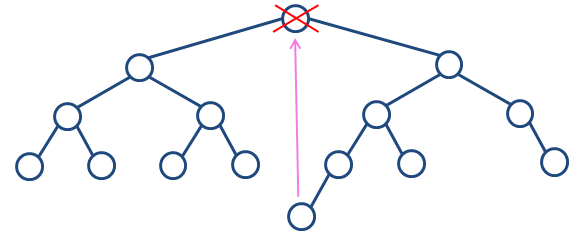 Image 1. Delete operation performed on the root. It holds dL=10/7 and dR=11/7, thus the replacement is taken from the right subtree. |
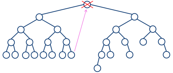 Image 2. Delete operation performed on the root. It holds dL=34/15 and dR=26/12, thus the replacement is taken from the left subtree. |
The task
You are given a sequence of Insert and Delete
operations which are to be applied on an originally empty AVL tree. Each
Delete operation is implemented by the proposed strategy. For Delete
operations performed on nodes having both subtrees non-empty, calculate
the number of replacements taken form the left subtree as well as the
number of replacements taken from the right subtree.
For example, consider inserting keys 3, 2, 7, 1, 5, 8, 4, 6, 9 into an originally empty AVL tree and then performing delete(1). Both single and double rotations result in a balanced tree in this case. On the other hand, if we had to perform delete(6), delete(1) and apply double rotation then another unbalanced node (with key 7) would appear in the tree.
Input
The first input line contains integer N. Next, there are N lines, each specifying one operation. Operation Insert is specified by capital letter 'I' followed by space and an integer key. Operation Delete is specified by capital letter 'D'
followed by space and an integer key. There are no duplicate keys in
the input and also there are no Delete operations of non-existent keys. All key values are positive and less than 109.
It holds N ≤ 1.5×10⁶.
Output
The output consists of one text line containing two non-negative integers L and R, separated by a space, where L is the number of Delete operations taking a replacement from the left subtree and R is the number of Delete operations taking a replacement from the right subtree.
Example 1
Input12 I 3333 I 2222 I 7777 I 1111 I 5555 I 8888 I 4444 I 6666 I 9999 D 6666 D 2222 D 7777Output 1 0 |
Insert 9999
           3333____________
       2222            ____7777
   1111            5555        8888
               4444    6666        9999
----------------------------------------
Delete 6666
           3333________
       2222            7777
   1111            5555    8888
               4444            9999
----------------------------------------
Delete 2222
           ________7777
       3333____        8888
   1111        5555        9999
           4444
----------------------------------------
Delete 7777
           ____5555
       3333        8888
   1111    4444        9999
----------------------------------------
Scheme 1. The tree in Example 1 in its final stages of developement.
|
Example 2
Input12 I 10 I 20 I 30 I 40 I 50 I 60 I 70 I 80 I 90 I 100 D 20 D 40Output 1 1 |
Insert 90
       __40__
     20      60__
   10  30  50    80
               70  90
------------------------------
Insert 100
       __40______
     20        __80
   10  30    60    90
           50  70    100
------------------------------
Delete 20
     __40______
   10        __80
     30    60    90
         50  70    100
------------------------------
Delete 40
     __50____
   10      __80
     30  60    90
           70    100
------------------------------
Scheme 2. The tree in Example 2 in its final stages of developement.
|
Example 3
Input37 I 21 I 13 I 29 I 8 I 18 I 26 I 32 I 5 I 11 I 16 I 19 I 24 I 27 I 31 I 33 I 3 I 6 I 10 I 12 I 15 I 17 I 20 I 23 I 25 I 28 I 30 I 2 I 4 I 7 I 9 I 14 I 22 I 1 D 33 D 26 D 21 D 13Output 0 3 |
Insert 1
                    ______________21______________
           _______13________                  ____29____
        __8___            __18            __26          32
      _5      11        16    19        24    27      31  33
     3  6   10  12    15  17    20    23  25    28  30
    2 4  7 9        14              22
   1
-------------------------------------------------------------
Delete 33
           _______13______________
        __8___                ____21________
      _5      11          __18            __26____
     3  6   10  12      16    19        24      __29__
    2 4  7 9          15  17    20    23  25  27      31
   1                14              22          28  30  32
-------------------------------------------------------------
Delete 26
           _______13______________
        __8___                ____21________
      _5      11          __18            __27__
     3  6   10  12      16    19        24      29__
    2 4  7 9          15  17    20    23  25  28    31
   1                14              22            30  32
-------------------------------------------------------------
Delete 21
           _______13______________
        __8___                ____22______
      _5      11          __18          __27__
     3  6   10  12      16    19      24      29__
    2 4  7 9          15  17    20  23  25  28    31
   1                14                          30  32
-------------------------------------------------------------
Delete 13
           _______14____________
        __8___              ____22______
      _5      11        __18          __27__
     3  6   10  12    16    19      24      29__
    2 4  7 9        15  17    20  23  25  28    31
   1                                          30  32
-------------------------------------------------------------
Scheme 1. The tree in Example 3 in its final stages of developement.
|
Public data
The public data set is intended for easier debugging and approximate program correctness checking. The public data set is stored also in the upload system and each time a student submits a solution it is run on the public dataset and the program output to stdout and stderr is available to him/her.
Link to public data set