Underground Mines Robots Training
Members of the robotic department at International University of Antarctica are developing a new type of robots which are intended to work
autonomously in difficult conditions in deep rare-earth element mines.
Three robots labeled 1, 2 and 3 are currently available.
They are located in an experimental corridor which internal structure has been modified to mimic the expected condition in mines.
The corridor is divided into sections. The physical environment (terrain, obstacles, visibility etc.) is different in various sections to model
various possible environments in mine tunnels. Each section is assigned a time, called visit time. It is the time which an individually operating robots spends in the section during its movement through the section.
A robot operation is divided into moves. A move has always assigned a direction to it. In the move, a robot relocates itself from its starting sector in the given direction to succesive adjacent sectors in the given direction. The move length is the number of sectors the robot visits in the move, including the start and the end sector of the move.
The time a robot spends in one move is equal to the sum of the visit times of all sectors which robot visits in one move, including the start and the
end sector of the move.
The robots operate in sequential fashion, that is, always only one robot is performing a move while the other two are standing in their current sectors
and await further commands.
The control center operates the robots in the following fashion:
A sequence of commands is prepared in advance. Then, the sequence is sent to the robots, one by one. Each successive command is sent immediately
after a robot executing the previous command terminates its execution.
A command consists of three numbers which specify the label of the robot, the direction of its move -- to the left or to the right in the corridor --
and the length of the move. The length of move is the number of the sectors in which the robot operates during the move, including the
start and the end sector of the move.
When a robot cannot continue its move to the next sector, because it is at the end of the corridor, it halts the execution of the command, informs the center about premature termination of the move and remains in the sector. Immediately after that the next command is issued.
All robots share so called radius of influence R which is a positive integer. A sphere of influence of a robot is the set of all sectors which distance from the sector in which the robot is currently located is less or equal to R. The distance of two sectors is equal to one plus the number of sectors between them.
A distance from a sector to itself is 0. As a robot moves through the sectors its sphere of influence moves with it.
When a robot is moving through a sector which is in the sphere of influence of at least one other robot, the robots communicate intensely and it slows
down the progression of the first robot through the sector. The time the first robot spends in the sector in such case is equal to the sector visit time multiplied by 2. When a robot is moving through a sector which is outside the spheres of influence of other two robots it spends exactly the sector visit time in the sector.
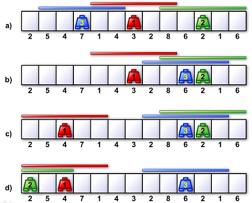 Image 1. Positions of robots in the corridor during a training consisting of three moves. The sector visit times are shown bellow their corresponding sectors. The horizontal bars depict the spheres of influence of robots, the radius of the sphere of influence is 2. Scheme a) depicts the configuration at the beginning of the training. Schemes b) c) and d) depict the configurations after each of three successive commands. b) The first command sends robot 3 to the right, move length is 7. c) The second command sends robot 1 to the left, move length is 4. d) The third command sends robot 2 to the left and prescribes the move length to be 20. However, the robot has to terminate the move prematurely after it finishes its activity in the leftmost sector. Thus, the resulting move length is only 11. The time spent in the first move is 55, the time spent in the second move is 19, the time spent in the third move is 81. The total time spent in all three moves is 155. The schemes illustrate Example 1 below. |
The task
You are given a corridor and the visit times of each sector in the corridor. Also, you are given the radius of the sphere of influence the robots and the initial positions of the robots in the corridor.
Finally, you are given the list of the robot move commands.
Calculate the total time robots spend in their moves.
Input
The first input line contains five integers Len, Rad, Sec1, Sec2, Sec3 separated by spaces.
Len is the number of sectors in the corridor, the sectors are labeled 0,1, ..., Len−1.
Rad is the radius of the sphere of influence of each robot.
Sec1, Sec2, Sec3 are the labels of the sectors in which robots 1, 2 and 3, respectively, stand at the beginning.
The next line contains a list of Len positive integers separated by space. The values in the list represent the visit times of all sectors in the corridor
in order form left to right.
The next line contains one integer Comm, the number of commands.
Next, Comm lines follow. Each describes one command and it contains three integers r, dir, m separated by spaces.
Value r is a robot label, value d describes the direction of the robot move, value m is the length of the move and it is always positive. Direction to the left is
described by dir = 0, direction to the right is described by dir = 1.
It holds, 2 ≤ Len ≤ 104, 1 ≤ Rad ≤ 103, 1 ≤ Comm ≤ 105.
Input data reliability
Note that all input data follow strictly the specification given here. There is no need to write a code which verifies whether the data comply with the specification.
Output
The output contains one text line with one integer representing the total time robots spent in their moves.
Example 1
Input13 2 6 10 3 2 5 4 7 1 4 3 2 8 6 2 1 6 3 3 1 7 1 0 5 2 0 20Output
155The data of Example 1 are depicted in Image 1a).
Example 2
Input6 1 1 2 3 5 5 5 5 5 5 6 3 1 2 2 1 3 1 1 4 1 0 4 2 0 4 3 0 4Output
175
Example 3
Input8 10 3 2 4 8 7 6 5 4 3 2 1 8 2 1 2 2 1 2 2 1 2 2 1 2 2 1 2 2 1 2 3 0 2 3 0 2Output
112
Public data
The public data set is intended for easier debugging and approximate program correctness checking. The public data set is stored also in the upload system and each time a student submits a solution it is run on the public dataset and the program output to stdout and stderr is available to him/her.
Link to public data set